Introduction to Electric Valve Actuators
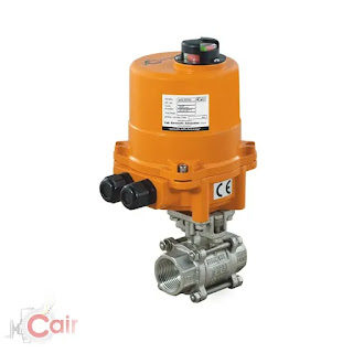
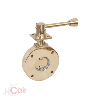
It is possible to replace pneumatically operated valves with motorized valves in many industrial control applications. Electric motors and electricity are used to operate a motorized valve. Through linkages (brackets and couplings) or directly mounted on the valve shaft, the spindle of the valve is connected to the motorized (electric) actuator. Globe, gate ball, and butterfly valves are the most commonly operated by electric actuators.
Since electric actuators are easy to interface with control systems, they are widely used in control systems. The control signals are also electrical, so the same conduit or conduit paths can be used. Unlike fluid power (pneumatic), electricity is typically available and can be run over long distances. When working in hazardous locations, special construction and wiring options must be considered. Electrical actuators have the following main advantages:
Electricity is usually readily available and can be easily routed to actuators over long distances.
Power can be controlled easily, and auxiliary control signals can be provided with the same "runs" as power.
The diagnosis of electrical faults is often easier than that of air or hydraulic faults.
The valve can be operated manually, semi-automatically, or automatically using electric motors. In addition to opening and closing valves, motors are used to position valves to any opening for control purposes. It is possible to design the actuator for valve types that require multi-turns or quarter-turns. Globe valves and gate valves require many turns of the actuator to open or close. In the case of the butterfly, plug, or ball valves, the actuator has to move only 90° to open or close the valve fully.
A motor is used in electrical actuators. It can be a single-phase or a three-phase motor. It is also possible to use DC motors. In order to open or close the valve, the motor moves forward or backward. Depending on the horsepower of the motor and the gearbox, the motor torque is determined.
A gear arrangement is provided inside the gearbox to reduce the high speed of the motor and increase its power. A typical electric actuator has a high reduction ratio, and the gearbox is always self-locking to prevent accidental closing or opening.
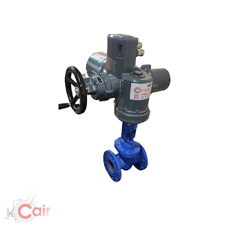
Hand wheel and clutch: In case of power outages or interruptions, the actuator (valve) can be operated manually by the hand wheel. There is a manual clutch arrangement that engages the hand wheel and disengages the gearbox.
In order to protect the motor control switch from the surrounding environment, the switch is located inside the actuator. A switch (contactor or solid state switch), control circuitry, and motor protection are included. Using the motor control system, you can open and close the valve in any direction, as well as proportionally.
Limit switches and torque switches are used to stop the actuator at its end position (i.e. fully open or fully closed). The motor is stopped when the valve reaches its end position and one of the limit switches operates. As a result of high amp draw caused by driving too much torque, torque switches are provided to prevent the actuator from overloading.
We are the leading electrical actuators manufacturer in India. We offer various types of industrial valves like motorized ball valves, motorized butterfly valves, motorized control valves, and many more.


Comments
Post a Comment